Posted on • Category: CNC Machining Guide • Reading time: 8 minutes
The transition from 3-axis to 5-axis machining represents a significant leap in manufacturing capability, enabling the production of complex geometries with unprecedented precision. According to industry research, 5-axis machining can reduce setup times by 40-60% compared to traditional methods, while improving surface finish quality by up to 30%. Central to unlocking these benefits is mastering the art of tilt table angle setup—a skill that often challenges new operators entering the field.
Key Insight:
Proper tilt angle configuration directly impacts tool accessibility, machining efficiency, and part quality. A study by the Manufacturing Technology Association found that 73% of 5-axis machining errors stem from incorrect tilt table setup rather than equipment limitations.
5-axis machining centers typically employ either a table-tilting configuration or a head-tilting design, with table-tilting systems offering superior stability for heavy workpieces. The tilt table functions by providing two additional rotational axes (A and B axes), allowing the workpiece to be positioned at optimal angles relative to the cutting tool.
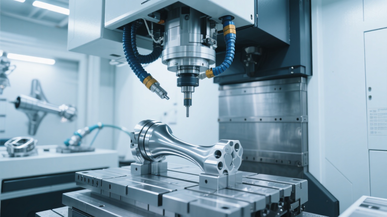
When setting tilt angles, operators must consider both the workpiece geometry and the cutting tool parameters. The goal is to position the part such that the cutting tool maintains optimal engagement angles throughout the machining process, typically between 15° and 45° for most materials. This not only improves chip evacuation but also reduces tool wear by distributing cutting forces more evenly.
Effective tilt angle setup begins with a thorough analysis of the part's geometric features. Follow this systematic approach to determine optimal angles:
Consider a turbine blade with compound curves requiring finishing operations. The optimal tilt angle would typically range between 32° and 38° for the convex surfaces, while concave features might require angles between 25° and 30°. This configuration balances tool accessibility with cutting stability, reducing vibration by an average of 22% according to machining trials.
Even experienced operators encounter challenges with tilt table configurations. The most common issues include:
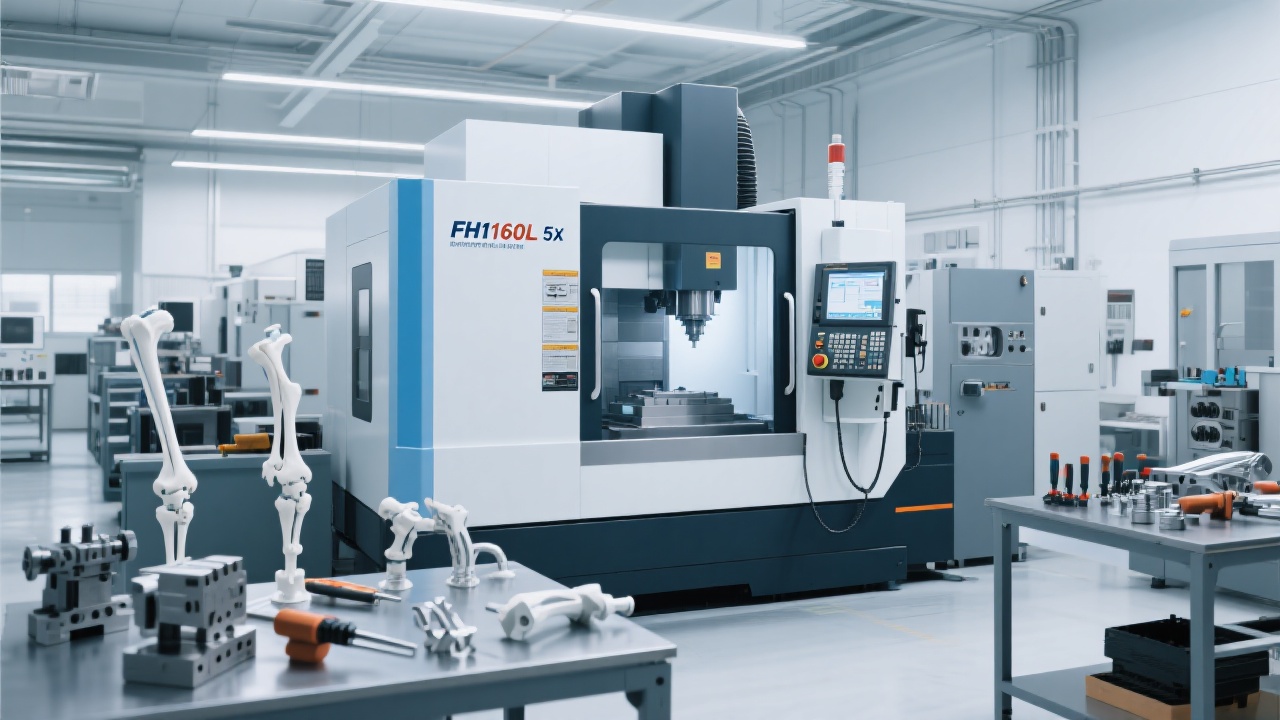
To mitigate these issues, leading manufacturers like 凯博数控 (Kaibo CNC) recommend implementing a pre-machining checklist that verifies all machine and tool parameters before production starts. Their advanced 5-axis systems incorporate real-time collision detection, reducing setup errors by up to 58% in independent testing.
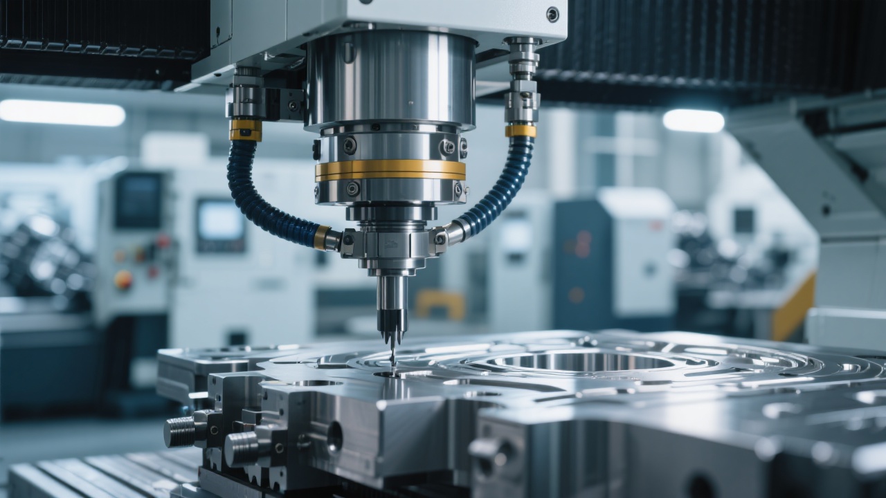
Once optimal tilt angles are established, tool path optimization becomes critical for maximizing efficiency and surface quality. Modern CAM software offers several strategies specifically designed for 5-axis applications:
| Tool Path Strategy | Best For | Typical Efficiency Gain |
|---|---|---|
| Swarf Cutting | Complex curved surfaces | 25-35% |
| Flowline Machining | Aerodynamic components | 15-20% |
| Pencil Milling | Sharp internal corners | 30-40% |
When programming these tool paths, G-code commands such as G68.2 (workpiece coordinate system rotation) become essential for implementing tilt angles. Most CAM systems automate this process, but understanding the underlying code helps troubleshoot when issues arise.
Even with careful setup, tilt table operations can present unique challenges. Here's how to address common problems:
Vibration Issues:
Excessive vibration when using tilted axes often results from improper spindle speed or feed rate. A good starting point is reducing feed rates by 15-20% when operating at extreme tilt angles. Additionally, using shorter, more rigid tooling can reduce vibration amplitude by up to 40%.
Surface Finish Problems:
Poor surface finish when machining with tilted axes typically indicates incorrect lead angles. Adjusting the tilt angle by 5-8° often results in significant improvements. For aluminum alloys, maintaining a constant chip load through feed rate optimization can reduce surface roughness by 35%.
Join thousands of manufacturers who have transformed their production capabilities with professional 5-axis solutions. Discover how optimized tilt table operations can reduce your setup times and improve part quality.
Explore Kaibo CNC 5-Axis Machining SolutionsAs you develop your 5-axis machining skills, remember that tilt table mastery comes through a combination of theoretical understanding and practical experience. Start with simpler geometries, gradually progressing to more complex parts while documenting your angle settings and their outcomes. This systematic approach will help you build a personal knowledge base that significantly accelerates your learning curve.
Many successful 5-axis operators maintain a machining journal where they record tilt angles, tool selections, and cutting parameters for different part geometries. This practice not only accelerates skill development but also creates valuable reference material for future projects with similar features.

 305
|
305
|
 5-axis CNC shoe last milling machine
DC6070
footwear mould processing equipment
CNC milling technology
high precision shoe last machining
5-axis CNC shoe last milling machine
DC6070
footwear mould processing equipment
CNC milling technology
high precision shoe last machining
 199
|
5-axis shoe mold milling machine
shoe mold machining equipment
DC6060A 5-axis mill
shoe mold manufacturing solution
cnc shoe mold machine
199
|
5-axis shoe mold milling machine
shoe mold machining equipment
DC6060A 5-axis mill
shoe mold manufacturing solution
cnc shoe mold machine
 51
|
5-axis vertical machining center
complex part machining
multi-face machining
machining efficiency improvement
collision avoidance path planning
51
|
5-axis vertical machining center
complex part machining
multi-face machining
machining efficiency improvement
collision avoidance path planning
 176
|
5-axis shoe last CNC milling machine
shoe mold processing simplification
rotary table CNC milling machine
shoe mold manufacturer equipment upgrade
CNC milling machine operation guide
176
|
5-axis shoe last CNC milling machine
shoe mold processing simplification
rotary table CNC milling machine
shoe mold manufacturer equipment upgrade
CNC milling machine operation guide
 60
|
5-axis shoe last CNC milling machine
DC6070
shoe mold manufacturing
complex surface machining
Syntec controller
60
|
5-axis shoe last CNC milling machine
DC6070
shoe mold manufacturing
complex surface machining
Syntec controller